Call Us 401-847-7960 | sales@ab-marine.com

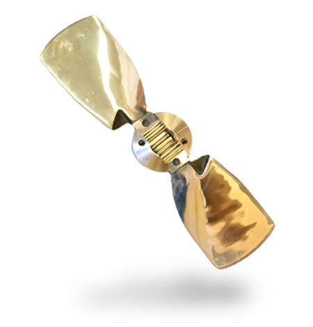
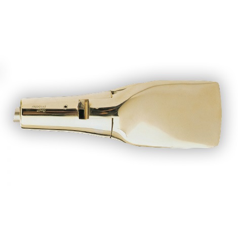
GORI 2-Blade Propeller

Suitable for sailing vessels fitted with engines up to 50HP.

The geared blade design ensures that both blades open and close together. This gives less vibration ahead and astern. Under sail, the blades close simultaneously removing the need for banding the blades together or worrying about one falling open causing an increase in drag.

The 2-blade propeller is available in diameters from 11.5” ~ 18” for shaft and saildrive installations. They are made for both LH and RH rotation installations.

Ahead: GORI efficiency is better than most 2 ~ 3 blade feathering and folding propellers

Astern: GORI has an efficiency equal to or better than most 2 ~ blade fixed, feathering & folding propellers

Sailing: Extremely low drag

Calculate Prop Size
Gori Propeller 2 Blade

2-Blade Standard Shaft

Diameter Pitch Range Rotation Max Shaft Dia.
11.5 8 + 9.5 RH ~ LH 1.125 ~ 30mm
12.5 8 RH 1.125 ~ 30mm
13 9 RH ~ LH 1.125 ~ 30mm
14 9.5 RH ~ LH 1.125 ~ 30mm
15 10 + 12 RH ~ LH 1.125 ~ 30mm
16.5 11 + 13 RH ~ LH 1.375 ~ 35mm
18 13 + 15 RH 1.375 ~ 35mm

2-Blade Saildrive

Diameter Pitch Range Rotation SD Unit
11.5 8 RH DV8 / MB2A
11.5 9.5 RH DV10
12.5 8 RH DV10
12.5 8 RH Bukh ~ Volvo ~ Yanmar
13 9 LH Bukh ~ Volvo ~ Yanmar
14 9.5 LH Bukh ~ Volvo ~ Yanmar
15 10 + 11 + 12 LH Bukh ~ Volvo ~ Yanmar
16.5 11 + 13 LH Bukh ~ Volvo ~ Yanmar
18 11 + 12 + 14 LH Bukh ~ Volvo ~ Yanmar
DiagramsInstallation + Maintenance
GORI 2-Blade Measurement Table

Gori-2-blade-Measurement-Table


Propeller and Shaft Clearance Dimensions

Prop_and_shaft_dimensions
A. Forward edge of propeller hub (start of taper) to aft edge of cutlass bearing
B. Shaft Diameter
C. Distance from shaft centerline to hull at forward edge of hub
D. Distance from shaft centerline to hull at end of shaft thread
E. Distance from rudder/skeg to end of shaft
F. Distance from rudder to start of taper/forward edge of hub

Saildrive Installation
Please read these instructions carefully before installing your new GORI propeller

Parts List:

(1) Hub – 1 x each
(2) Blades – 2 x each
(3) Pins – 2 x each
(4) Washer – 1 x each
(5) Shaft nut – 1 x each
(6) Split pin – 1 x each (not used on all installations)
(7) Allen screws – 2 x each
(8) Allen screws – 2 x each
(9) Locking bolt – 1 x each
(10) Collar zinc – 1 x each … 2 x halves
(11) Zinc screws – 4 x each
(12) Loctite 243 – 1 x bottle
(13) Allen key – 4mm
(14) Allen key – 5mm
Gori2blade_saildriveInstall

A) Take the propeller apart – note that there are two allen screws (7,8) that lock each of the blade pins (3) in place. Note that the blades, pins and hub are all marked carefully so as to re-assemble in the correct location.

B) Check that the hub (1),fits onto the output shaft of the saildrive leg. The hub has a matching spline and so simply slide it on. Check that the shaft nut (5),threads on to the end of the output shaft

C) Ensure that the washer (supplied with the saildrive unit) is in place at the fwd end of the output shaft. Now grease the output shaft on the saildrive with some water resistant grease and slide the hub back on.

D) Install the GORI supplied shaft nut (5), onto the shaft and tighten to 70 ft/lbs. Now smear some loctite (12) onto the threads of the lock bolt (9). Place the washer (4) in place and tighten the lock bolt (9), into the output shaft. It is very important to always use the GORI supplied propeller nut for the installation. An incorrect nut can lead to loss of the propeller, part of the propeller or cause an electrical connection between the propeller and the saildrive.

On older saildrive models there may be holes drilled through the male thread area at the end of the shaft. If so then align these holes with the holes on the lock bolt (9) and insert the split pin (6) and bend over.

E) Lightly grease the moving parts of the blades (2) and re-assemble the blades with the pins (3). Be careful to place pins, blades and hub in the same numbered locations.

F) Apply locktie (12), to the allen screws (7,8), screw them tightly into the holes at the aft end of the propeller hub. Be sure that the blade pins (3) are smooth and neat on the outside of the hub…this will ensure that the allen screws have seated themselves into the dimple on the pin. Remember there are 2 per blade pin.

G) Check that the blades will operate freely in all directions from open to closed.

Warning:

– Do not start the engine while the boat is out of the water
– The prop may have sharp edges… be careful not to cut yourself
– Make sure the blades do not open or close suddenly and trap your fingers
– Stop the engine before diving or swimming in the vicinity of the boat
– Propeller blades can cause considerable damage when rotating … be careful.
– Do not remove fish nets, rope or similar from the prop with the engine running.
– Check that the prop works in both fwd and reverse before each trip. If any strange sounds or vibrations are noticed coming from the propeller stop the engine and investigate the reasons/solve the problem.

Download the 2 Blade Saildrive Installation Instructions as a PDF

Standard Shaft Installation
Please read these instructions carefully before installing your new GORI propeller

Parts List:

(1) Hub – 1 x ea
(2) Blades – 2 x ea
(3) Pins – 2 x ea
(4) Shaft nut – 1 x ea
(5) Allen screws – 1 x ea
(6,7) Allen Screws – 4 x ea
Gori2BladeStandardShaftInstall
A) Take the propeller apart – note blades, pins and hub are marked for re-assembly.

B) Check that the hub fits the shaft taper without interference form the key.
C) Check the nut on the shaft thread.

D) Mount the hub on the shaft and tighten the nut (4) to the shaft. Use 7/8th socket … 22mm.
E) Install the allen screw (5) into the hub to lock the shaft nut. Do this by first smearing the threads with the enclosed Loctite–243. Tighten the screw in place using the allen key supplied.
F) Grease the moving parts of the blades-gears- with water resistant grease. Mount the blades (2) and the pins (3) to the hub. Be sure that you mount them in accordance to their numbers. ie #1 and #2.
G) Install allen screws (6,7) into aft end of hub using Loctite -242, on the threads. The second screw is a locking screw. Be sure tighten both in place.
H) Check that the blades move freely from open to close.

Warning:

– Do not start the engine while the boat is out of the water
– The prop may have sharp edges… be careful not to cut yourself
– Make sure the blades do not open or close suddenly and trap your fingers
– Stop the engine before diving or swimming in the vicinity of the boat
– Propeller blades can cause considerable damage when rotating … be careful.
– Do not remove fish nets, rope or similar from the prop with the engine running.
– Check that the prop works in both fwd and reverse before each trip.
– If any strange sounds or vibrations are noticed coming from the propeller stop the engine and investigate the reasons/solve the problem.

Download the 2 Blade Standard Shaft Installation Instructions as a PDF
Would you like to discuss GORI propellers without obligation?

If you are interested in our GORI products, we would like to send you further information.
Please fill out the form below and we will contact you immediately. Or feel free to call us at 401-847-7960

    Your Name (required):

    Your Email (required):

    Confirm Email (required):

    Your Telephone (required):

    Model of Interest: 2-Blade3-Blade3-Blade Single Pitch4-BladeRace SeriesAll Models

    BOAT INFORMATION

    Boat Make and Model (required)

    Waterline Length (required)

    ENGINE INFORMATION

    Number of Engines (required)

    Engine Manufacturer (required)

    Model Number (required)

    Engine hp/kW (required)

    Max Rated RPM (required)

    Type of Gearbox (recommended)

    hydraulicmechanicalsail drive

    Forward Gear Ratio (required)

    Prop Installation Type:

    1. P Bracket Strut2. Shaft Log3. Aperture4. Saildrive


    Existing Prop Size:

    Shaft Diameter:     Prop Diameter:     Pitch:    

    # of Blades:   Right HandLeft Hand

    Additional Notes: